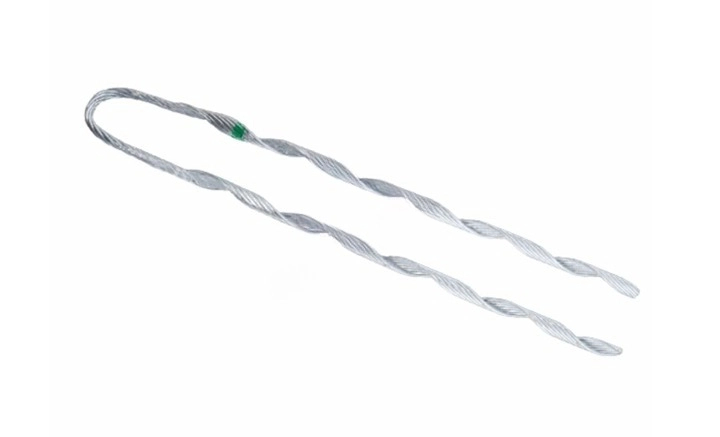
A false dead end refers to a point in the electrical distribution system where a conductor terminates or anchors. It creates an illusion that the point ends at that point when it actually continues. It serves as a structural support for the conductor like an actual dead end. This helps provide tension and stability to the line. False dead ends play a role in design, maintenance, and reliability of power distribution systems. They help in balancing and distributing electrical loads across the network. False dead ends allow for greater flexibility in the design and layout of distribution systems. It also enables engineers to route circuits without extensive modifications to extensive infrastructure.
Size and diameter of a false dead end
The size and diameter of a false dead end depends on several factors. This is including the type of conductor, the tension in the line and the specific requirements of the installations. Typical sizes and diameters range from 0.2 inches to over 1 inch in diameter. Hardware and accessories can include components that are a few inches to several feet in length. The following are the key factors that influence the size and diameter of the false dead ends.
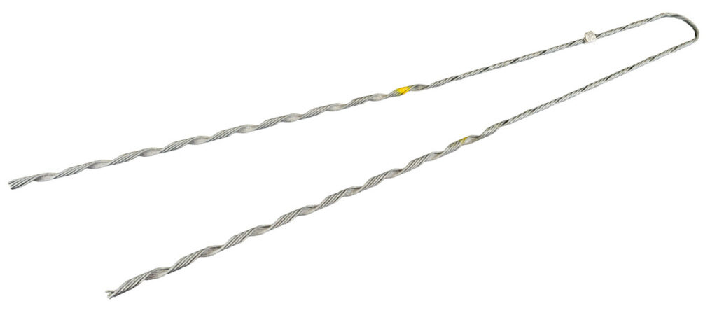
- Conductor type and size – conductors can be from different materials like aluminium, copper, or steel-reinforced aluminium. The physical size of the conductor shows the sizes of the clamps and other hardware.
- Tension and mechanical load – the mechanical tension in the conductor due to its weight and forces is also a factor. High tension lines need strong dead end hardware to handle the stress.
- Electrical load – higher voltage lines need components that can handle greater electrical stress and provide enough insulation. This affects the size and type of insulators and other hardware used. The current carrying capacity of the conductor influences the design of the dead end.
- Environmental conditions – exposure to environmental conditions can also influence the size selection. The dead end components should withstand wind, rain, ice, and extreme temperatures. Installations in areas prone to seismic activities, high winds, or snowfall need larger components to ensure stability.
- Installation and maintenance needs – ease of installation and maintenance can influence the selection of components. Most preferred components are components that need minimal maintenance.
- Regulatory and Safety Standards – All components must meet local and international safety and performance standards. These standards can dictate minimum sizes and material requirements.
- Design and engineering considerations – the layout and configuration of the power distribution system impacts the design of the dead ends.
Selecting the best false dead end
Selecting the proper false dead ends is crucial for the overhead and electrical applications. The selection process depends on various factors to ensure they meet the necessary requirements. Proper selection also helps to ensure safety, reliability and performance. Additionally, it is advisable seek expert help when selecting the false dead end for your application. The following are the factors to consider when selectin the false dead ends.
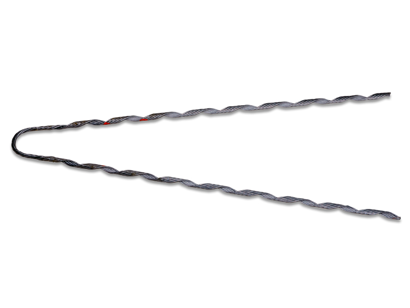
- Conductor specifications – determine the type of conductor and measure the conductor diameter. This is to ensure compatibility with the dead end. Assess the current-carrying capacity of the conductor.
- Mechanical load requirements – calculate the tension in the conductor. Consider factors like span length and conductor weight. Check the extra forces as wind load, ice accumulation and temperature changes.
- Electrical load and insulation needs – ensure the dead end components can handle the voltage levels. Select insulators that are suitable for the voltage and environmental conditions. This helps to prevent electrical discharge.
- Environmental conditions – choose materials that can withstand local weather conditions including corrosion resistance.
- Hardware components – match the clamp sixe to the conductor diameter and tension requirements. Ensure the anchor points are strong enough to handle the tension and are compatible with the structure.
- Design for durability and maintenance – select materials with high durability and low maintenance needs. Choose components that are easy to install and allow for straightforward maintenance procedures.
- Redundancy and reliability – consider designs that include redundant paths to ensure continued operation if one fails. Ensure the false dead ends integrates into the system configuration.
- Regulatory and Safety Standards – Ensure all components meet relevant standards like IEEE, ANSI). Incorporate safety margins into your design to account for unexpected loads and stresses.
Installation procedures for false dead ends
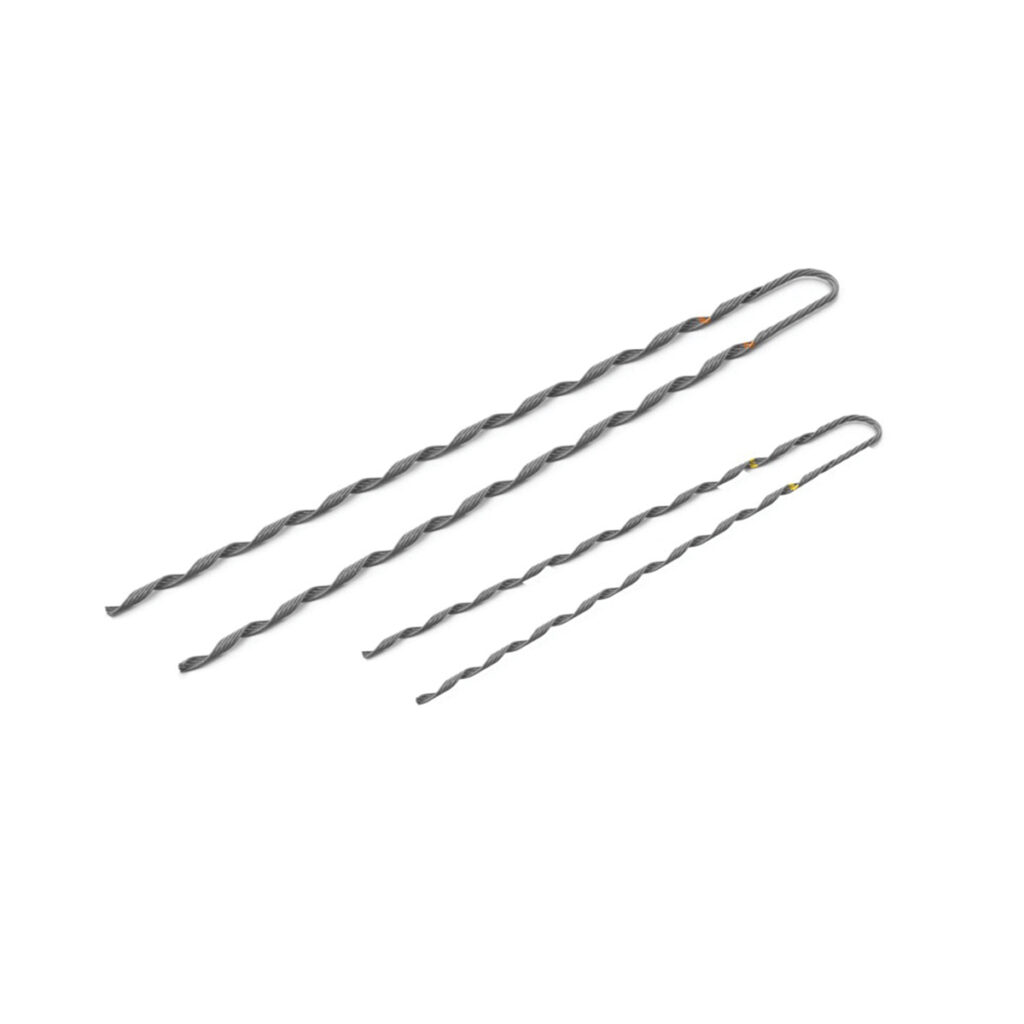
Installation of false dead ends involves a series of steps to ensure the secure termination and support of conductors. Also, it is advisable to follow the provided manufacturer’s guidelines during installations. This ensures the dead end installation is secure, reliable, and compliant with industry standards. The following is a basic guide on the installation of false dead ends.
- Preparation – conduct a thorough inspection of the installation site to identify any potential hazards. Follow all safety protocols like wearing personal protective equipment.
- Determine the location – mark the point on the pole or tower where the false dead end will install. Ensure the structure can support the extra load and stress from the dead end installation.
- Install anchor points – mark the exact locations for anchor points on the pole or tower. Drill holes at the marked locations to the specified diameter and depth.
- Prepare the conductor – cut the conductor to the required length allowing for enough slack. Strip the insulation from the end of the conductor to expose the bare wire.
- Install dead end clamp – select the dead end clamp that matches the conductor diameter and tension needs. Position the conductor within the dead end clamp and ensure it seats properly.
- Attach insulators – choose the suitable type of insulator based on the system’s voltage and environmental conditions. Attach insulators to the anchor points ensuring they align and fasten properly.
- Tension the conductor – connect a tensioning device to the conductor to apply the necessary tension. Apply tension according to specified requirements for the conductor type and span length.
- Testing – perform electrical tests to ensure proper continuity and insulation. Conduct load tests to verify the mechanical integrity of the installation.
- Documentation – keep detailed records of all the installation processes. This is including dates, locations and tools and components used.
Inspection and maintenance of the dead ends
Regular inspection of false dead ends helps to maintain the safety and reliability of overhead and electrical installations. It also helps to identify and address potential issues that may lead to failures. This ensures continuous and safe operations. Additionally, it is advisable to conduct professional inspections once in a while. The following is a guide on how to inspect false dead ends.

- Safety preparations – ensure all inspection personnel wear suitable safety gear. De-energize the line if it needs close contact with the components.
- Visual inspection – look for signs of wear, damage or corrosion on all components of the false dead ends. Ensure all components are properly aligned and that there are no visible signs of sagging.
- Mechanical inspection – verify that the tension in the conductor is appropriate and the support structure is intact. Inspect the anchor points for signs of loosening, corrosion or structural damage.
- Electrical inspection – inspect the insulators for cracks, chips, or contamination that could affect their insulating properties.
- Structural inspection – look for environmental damage caused by weather conditions like corrosion.
- Cleaning – clean any dirt, debris, or vegetation around the false dead end components to ensure clear access.
- Mechanical maintenance – check all bolts, nuts, and clamps for tightness. Apply lubricant to any moving parts or joints to prevent rust. Replace any parts showing signs of wear such as damaged clamps, bolts or insulators.
- Electrical maintenance – inspect insulators for cracks or damage to maintain electrical insulation. Check the conductor for signs of wear or corrosion
- Structural maintenance – apply anti-corrosion treatments to metal components as needed. Repair or replace damaged conductors.
- Tension adjustment – measure the tension in the conductor to ensure it meets the specified needs. Use a tensioning device to apply the correct tension and secure the conductor.
Frequently asked questions
Size and diameter of the false dead end depends on factors like type and diameter of the conductor, mechanical loads and tension. It also depends on electrical load, environmental conditions and specific design and configuration of the electrical system.
Regular maintenance is crucial for ensuring the safety, reliability and longevity of the electrical distribution system. It helps identify and address potential issues before they lead to failures.
